Example for Table 1. WT-01 B Concrete Thrust and Anchor Block Installations - Notes 01-26-2022 Updated.

Taper Thrust Block Details Dwg Thousands Of Free Autocad Drawings
G-6 - Typical Concrete Encasemen t.
. Download thousands of free detailed design planning documents including 2D CAD drawings 3D models BIM files and three-part specifications in one place. 4 REBAR WITH MASTIC COATING WHERE PIPE MUST BE ANCHORED TO THRUST BLOCK. Lincoln county public works 115 w.
W-1 Typical Trench Detail W-2 Fire Hydrant Assembly W-3A B C D Concrete Thrust Block Detail W-4 Water Service Detail ¾ and 1 Meter W-5 Water Service Detail 1 12 and 2 Meter W-6A B C Air Valve Installation 3 W-7 4 and 6 Blow-Off Assembly W-8 2 and 4 Dead-End Flush-Out. DWG SECTION 5 - PIPELINES THRUST BLOCKS. Temporary Blow-Off Assembly PDF CAD Permanent Blow-Off Assembly PDF CAD Air-Release Manhole PDF CAD Fire Hydrant Assembly PDF CAD Tapping Sleeve and Valve Assembly PDF CAD Standard Bore Encasement PDF CAD Vertical Bend Rodding and Blocking Detail PDF.
Thrust block bend details note 1. These documents are used on Capital Projects as well as private development projects. Standard Drawings - Water.
Types of Thrust Blocks Bearing Gravity Bearing Thrust Block Bearing Area ft 2 Safety Factor Thrust Force lbs Bearing Capacity of Undisturbed Soil lbsft2 Undisturbed Soil Bearing Area 45 45 Soil Bearing Strength SB Soil SB lbft2 Muck 0 Soft clay 1000 Silt 1500 Sandy silt 3000 Sand 4000 Sandy clay 6000 Hard clay 9000 Bearing Thrust Block Ht h. The tool assesses both the short term and long term expected costs and benefits. Standard Design for Concrete Thrust Blocks.
CAD drawings need to be opened up in Chrome or Firefox. 4INSTALL THRUST BLOCK SO THE HORIZONTAL X AND VERTICAL Y DIMENSIONS OF THE THRUST. 8-inch 90 bend Line Pressure 100 psi From Table.
301 1998 BLOCKING FOR WATER GATE AND BUTTERFLY VALVES 302-1 1998 JOINT RESTRAINT WITH TIE RODS DRAWING 302-2 1998 JOINT RESTRAINT WITH TIE RODS NOTES 303-1 1998 JOINT RESTRAINT FOR DUCTILE IRON AND POLYETHYLENE WRAPPED DUCTILE IRON WATER PIPES DRAWING 303-2 1998 JOINT RESTRAINT FOR. Seq-wat-1204-1 typical trench and bedding details within existing roads type k to n b seq-wat-1205-1 typical thrust block details mass concrete a seq-wat-1206-1 typical thrust and anchor blocks for valves b seq-wat-1207-1 typical thrust and anchor blocks for vertical bends a seq-wat-1208-1 typical restrained joint system dn 100 to dn 375 di mains a. Xlcpw standard detail and specifications2013 draft04_standard detailslcpw_ws-01dwg approved.
FY22 Watershed Discount Rate 225 08 for other work in 2021 Normalized Prices for use in FY2021 and earlier years. This drawing represents minimum standards. Typical Details of Anchor Block for Buried Pipes Laid on Slope Nominal Size DN150 and above 1.
Bearing area for thrust blocks shall. Would you like to receive periodic updates from the City Engineer. 12100 lbs 2000 psf 61 sqft Pipe area is based on largest actual inside diameter of ductile iron pipe.
Drawing valid only when used as shown and in conjunction with other fairborn issue date. G-3B - Typical Thrust Block Detail for Horizontal and Sag Vertical Details T Values G-4A - Typical Thrust Block Detail Vertical Crest Anchors. 1 Thrust blocks for pipelines 16-inch and smaller.
Precast Concrete Units for Valve Chambers. 5-1 STANDARD EASEMENT WIDTHS 120299 5-2 PIPE BEDDING TRENCH BACKFILL FOR WATER MAINS 032511 5-3 VALVE WELL INSTALLATION 032511 5-4 VALVE STEM EXTENSION 120299 5-5 CONCRETE VALVE BLOCKING 041113 5-6. For thrust blocks in existing or proposed roads or road rights of way provide a minimum one and one half 1-12 feet of soil cover unless otherwise directed or approved.
For bearing areas see detail drawing i-20. Any modifications to this detail shall first be. Constructed of 420-b-2000 concrete.
Depend on pressure and pipe size. Engineering specifications andor details. Typical Details of Thrust Blocks.
INSTALL AND TEST MAINLINE ACCORDING TO MANUFACTURERS INSTALLATION SPECIFICATIONS. A The dimensions and design details for concrete thrust blocks for pipe sizes 16-inch and smaller diameter are. VISTA IRRIGATION DISTRICT TABLE OF CONTENTS REV.
Detail of Test Conductor Connection to Pipe --- 228 Horizontal Thrust Block Diagram --- 229 Horizontal Thrust Block Dimensions Quantities For 11 ¼ 22 ½ Degree Bends --- 230 Horizontal Thrust Block Dimensions Quantities For 30 to 90 Degree Bends --- 231 Horizontal Thrust Block at Tees and Plugs --- 232. 100 psi x 121 lbspsi 12100 lbs Soil Bearing Strength 2000 psf Area of bearing required for thrust block is 61 sq. Pp passive soil pressure lbsft2 γ backfill soil density lbsft3 Hc mean depth from surface to the plane of resistance in feet centerline of a pipe or center of bearing area of a thrust block ft Cs soil cohesion lbsft2 Nφ tan245.
General Water Information Details. Fire Hydrant and Fire Service Details. Potable Water and Recycled Water Facilities.
THRUST AND ANCHOR BLOCKS AND PIPE RESTRAINT DETAILS. G-7 - Typical Pavement Patch for Private Paved Roads. WT-01 A Concrete Thrust and Anchor Block Installations 01-26-2022 Updated.
D-10 water main polyethylene wrap detail d-11 thrust restraint concrete thrust block details d-12 thrust restraint restrained joint pipe d-13 precast valve basin for pipes up to 16-inch diameter d-14 brick masonry valve basin d-16 typical 1-inch to 2-inch water service d-18 casing pipe under railroad track detail. REFER TO SPECIFICATIONS FOR TRENCH DEPTHS. Single Air Valve Chamber.
Concrete thrust blocks shall be. Design and Construction Standards Section is responsible for the Infrastructure Design Manual Standard Construction Specifications Standard Drawings and Product Approval. WT-01C Concrete Thrust and Anchor Block Installations 01-26-2022 Updated.
Thrust per 1 psi 121 lbs. Typical Details of Supports for Exposed Pipeworks Nominal Size DN150 and above 7. G-4B - Typical Thrust Block Detail Vertical Crest Anchors B Values G-5 - Typical Restraint Detail for Slopes Over 20.
A conventional thrust block at a vertical bend upward thrust is simply a block of concrete attached to the pipe with sufficient weight to counterbalance the thrust. A conventional thrust block at a vertical bend downward thrust would be similar to that for a horizontal bend but would bear on the trench floor rather than the wall. Contact Lauren Cartwright with any problems or concerns accessing the tool from this site.
Download thousands of free detailed design planning documents including 2D CAD drawings 3D models BIM files and three-part specifications in one place. WT-02 Valve Support Blocks 11-16-2007 WT-03A. Main street lincolnton nc 28092 phone 704 736-8497 fax 704 736-8499 suum qui u e tribuate l i n coln co u n t y n o r t h carol i n a consti tution thrust blocking detail 12312013 nts.
Air and Vacuum Valve Details. Register for our newsletter.

Thrust Block Details For Bends Dwg Thousands Of Free Autocad Drawings

Typical Thrust Block For Water Mains Dwg Thousands Of Free Autocad Drawings

Typical Thrust Blocking Details Dwg Thousands Of Free Autocad Drawings

Thrust Blocks
2
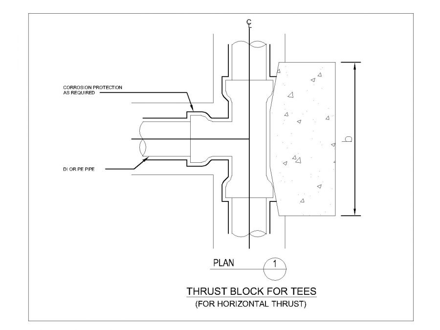
Thrust Block Details For Tees Dwg Thousands Of Free Autocad Drawings

Thrust Block For End Caps Details Dwg Thousands Of Free Autocad Drawings

T723 Thrust Blocks
0 comments
Post a Comment